Have you ever wanted to use MIDI commands to control electrical lights or appliances? This article will tell you how using a Raspberry Pi, the GPIO pins controlled by some open-source software from McLaren Labs on GitHub, and a nifty device called the IOT Relay. Using the Relay is an affordable and SAFE way to control 120 VAC sockets and it makes this project a breeze.
Introduction
One of the great things about the Raspberry Pi (there are many, you know) is its GPIO pins. GPIO stands for "general-purpose input/output". The GPIO pins are how your Raspberry Pi software can read voltages from external components, or how your software can control voltages.
Over the years, there have been a number of software libraries and packages for using the GPIO pins. One of the more recent ones is called "libgpiod" - the "d" is for device. A nice introduction to it is the one here:
That's only half of the problem. To control GPIO pins from MIDI we need some software to read from the MIDI system.
ALSA MIDI
ALSA is the "Advanced Linux Sound Architecture" and it provides the interface to the Linux MIDI system. ALSA provides two separate MIDI interfaces: one is the "raw" interface and the other is the "sequencer" interface.
- The "raw" interface exposes an external MIDI device as a serial byte interface.
- The "sequencer" (SEQ) interface provides a higher-level abstraction and knows about specific message types. This interface also enumerates the MIDI devices in your system and can alert about new devices being added, or devices being removed.
The SEQ interface can be daunting to get started with. But McLaren Labs has made a starter project available that shows how to do all the tricky things.
MIDI2GPIOD - how it works
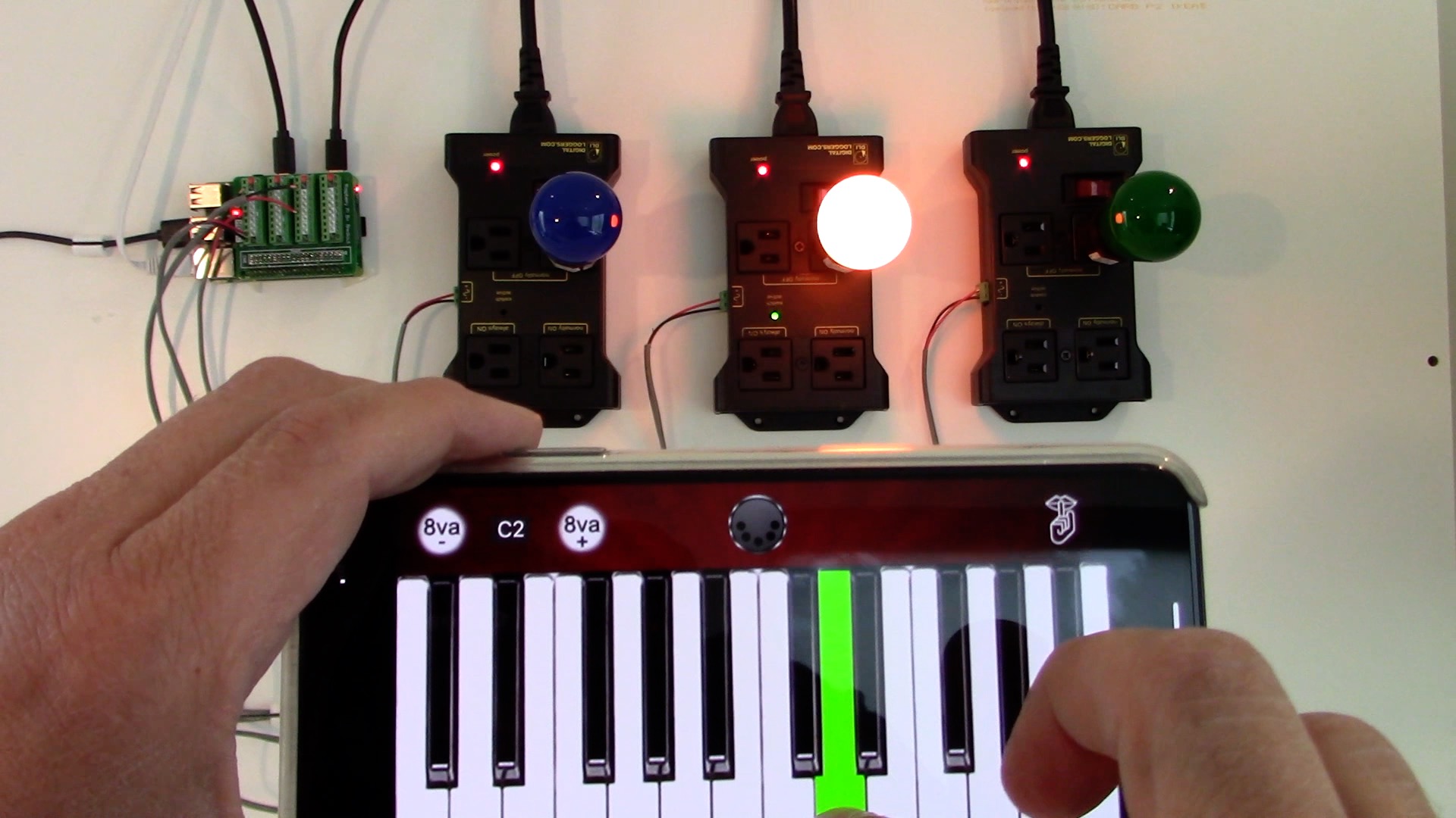
This program has been written to drive 3 specific GPIO outputs from 3 specific MIDI note events.
- Middle-C drives GPIO 25
- D drives GPIO 26
- E drives GPIO 27
For each, a "note-on" event maps to turning the GPIO "on" and the "note-off" event maps to turning the GPIO "off".
When launched, the program looks for a specific MIDI Device to receive events from. You can see the Devices (virtual or physical) in your system by using the aconnect command.
$ aconnect -i -o -l
This will show you the MIDI devices connected to your system. Each MIDI device has a "client name" that is used to identify it. By default, our midi2gpiod program looks for a client named "rtpmidi". In other words - it is looking for MIDI events provided over the network by McLaren Labs' "rtpmidi" program. But you may have keyboards or sequencers in your system, and you can use one of those to drive the GPIO outputs.
Start up the midi2gpiod command with the name of the device you want to receive events from. You can include the port if you want, or omit it if it is zero.
$ ./midi2gpiod -p MyKeyboard:0
If the device name has spaces in it, put it in quotes.
$ ./midi2gpiod -p "LaunchKey 25"
You can also watch for events coming out of a sequencer. Just hook it up.
MIDI2GPIOD is Tenacious
Oftentimes in little projects like these, the order of starting up the system makes a difference. Do you need to attach the keyboard before starting midi2gpiod or after? What if you do it in the other order? Can you unplug the keyboard and reattach it?
To help simplify matters, midi2gpiod has been designed to be tenacious. If the keyboard is already present when midi2gpiod starts, then it registers itself with the ALSA SEQ system to receive events from the keyboard.
If the keyboard is not already present, midi2gpiod registers with the ALSA SEQ system to receive an event when new keyboards and sequencers are attached or started. If the new device matches the name, then midi2gpiod begins to receive events from it.
This little convenience feature helps make it easier to use the program. You could configure your system to run midi2gpiod at boot time to match a specific keyboard name. Then, when you plug in your MIDI keyboard to an USB port, it would "just work."
We like that.
IOT Relay
Using a GPIO pin to control a 120-volt AC outlet is a fairly common thing to do. It can also be slightly dangerous if you don't know what you're doing. That's where the IOT Relay really helps. This is a very affordable device that makes it incredibly easy to control lamps and other devices.
Take a look at this page here. And be sure to watch the video - it's great!
The IOT Relay has four electrical outlets, with three of them controlled by one GPIO pin. The four outlets work this way.
- one outlet is "always on"
- two outlets are "normally off" and turn "on" when the GPIO pin goes HIGH
- one outlet is "normally on" and turns "off" when the GPIO pin goes HIGH
The assignment of these outlets to these functions is a very clever design choice we think.
Conclusion
Use MIDI on a Raspberry Pi to control electrical lights or other appliances. This article showed you what you need.
- a Raspberry Pi
- McLaren Labs
midi2gpiodprogram - an IOT Relay
Have some fun with MIDI and 120 VAC! And be sure to share a comment or a picture if you do.